您是否没有在项目网站上支持桥梁或建筑物的深层基础的文件?你有没有想过你是否可以重复使用现有的深度基础来实现新的结构,或者从改造中携带更多的负载?有多种测试方法可以有助于确定未记录或未知的深度基础的几种特征,例如:估计安装长度,评估完整性和评估承载阻力。我们在Braun Intertecmanbet体育滚球的方法采用了对深基础的项目需求和可访问性。在这两部分文章中,我们将讨论测试方法的方法,我们在分析所收集的数据,测试方法的利弊,并通过案例研究。在第1部分中,我们将专注于低应变完整性测试,通常称为坑或SE-IR。
低应变完整性测试
低应变完整性检测是基于理论的y of one-dimensional stress wave propagation. An impact is applied at one end of the deep foundation to impart a stress wave and the response of the stress wave is measured with an accelerometer or geophone. Typically, both the accelerometer and impact point are at or near the top of the deep foundation. As illustrated in Figure 1, the stress wave travels along the deep foundation until meeting a change in the deep foundation’s properties (cross-sectional area, modulus of elasticity, or density) or in the soil resistance. Once it has met a change in property or soil condition, portions or all the stress wave is reflected back to the top of the deep foundation. We can use this test to both determine the relative integrity of the pile and to estimate the deep foundation length.

根据该方法评估深基础的深度完整性,我们在预期长度之前寻找应力波的反射或反射。良好完整的深层基础将具有清晰的桩脚趾反射,只有微小的变化对冲击时间和脚趾反射时的应力波。具有良好完整性的深层基础也可能具有负速度反射,通常由软土,螺旋钻摆动或鹅卵石移除引起的“凸起”导致较大的横截面积。另一方面,正速度反射表示从空隙,土壤包裹,颈缩或裂纹或脆性的混凝土中的阻抗减少。虽然评估可以识别显着的阻抗变化,但是不可能确定为何单独从低应变完整性测试发生阻抗变化。此外,看起来一个显着的阻抗变化可能不代表深基础的承载能力的显着变化。
由于该测试方法基于一维应力波传播,因此估计精度波速对于估计长度未知时的深基础长度至关重要。如果我们知道弹性模量和材料的密度,我们可以计算波速。对于钢材,我们知道波速约为每秒16,800英尺(FPS)。然而,估计木材,灌浆和混凝土的精确波速可能是棘手的。深基础的密度和弹性模量在用于木材桩或混合设计和混凝土的混合设计和强度的不同种类之间变化。通常,优质的混凝土的波速在11,000至15,000 fps之间。木材桩具有较大的8,000至15,000 FPS,以及一些出版物甚至更高。我们可以从这些深层基础上获得样品,并运行实验室测试以更好地估计给定深层基础的密度和/或弹性模量。这使我们能够更好地估计深基础的波速。
一种更简单且准确的估计波速的方法是使用多通道数据收集设备,该数据采集设备使用加速度计和仪表的冲击装置或两个加速度计。对于任一种选择,我们暴露了深基础的一侧。如果我们将加速度计安装在深基础顶部下方并用仪表锤冲击深基础顶部,我们可以测量冲击之间的时间和应力波触发加速度计。然后我们可以通过深基础计算实际波速,并使用它来估计深基础长度。类似地,我们可以沿着深基础侧面安装两个加速度计,沿着深基础侧面,测量应力波在加速度计之间通过,然后计算应力波的波速。
除了能够确切地识别为什么存在阻抗变化,以下是低应变完整性测试的一些额外考虑因素。
- 在深度基础的长度到直径比大于30的深度处获得可用数据是不可靠的。
- 低应变完整性测试不提供关于深基础阻力的信息。
- 由于凸起或相对强大的土壤/岩石产生的显着阻抗变化,沿着深基础的长度可能会掩盖脚趾反射或其他,阻抗的更大变化。
- 低应变完整性测试只能确定主要的缺陷或完整性问题。
- 当结果没有产生明确的脚趾响应时,测试可以不确定。
- 由于这些深基础类型的阻抗性质的固有变化,对具有H型“刺刀”或单管桩的复合深层基础部分的评估,例如具有H型桩“刺刀”或单管桩,通常是复杂的并且通常是不可靠的。
Case Study – Red Wing Recycling and RDF Project
After a fire destroyed enough of the existing City of Red Wing’s Recycling and RDF (refuse-derived fuel) facility to require razing the structure down to building’s floor slab in 2017, the City chose to rebuild on the existing site. Before rebuilding, three challenging questions needed to be addressed: what is the condition of the timber piling installed in 1982, can the existing timber piling handle revised design requirements based on current codes, and how to support proposed expansions to the existing facility. We performed low-strain integrity testing to validate that the actual pile lengths matched the pile records we had from the contractor.
To accomplish this, we excavated two test pits adjacent to the exterior foundation lines to expose the timber piles. Once the piles were exposed, we sounded, probed, and visually inspected the piles to confirm they were in good condition. For the low-strain integrity testing on this project, we mounted the accelerometer directly to the exposed timber pile using coupling grease and a machined aluminum block. We struck the top of the foundation directly above each timber pile location with the instrumented hammer at least three times to allow for us to average the collected data for calculations.
As discussed above, striking the top of the foundation a known distance above the accelerometer allowed us to more accurately determine the pile’s wave speed and length, which also improved our evaluation of the pile’s integrity. The low-strain integrity testing data, as shown Figure 3, resulted in calculated pile lengths that were within one foot of the reported pile lengths and indicated the piles were of good integrity. The end results of our investigation and analysis were that no additional piling was need under the existing building, resulting in huge cost savings.

案例研究 - 查尔斯湖港
该项目包括在查尔斯湖港口的现有泊位的康复。我们被要求评估现有木材桩在泊位的长度,完整性和估计。我们将讨论我们如何评估本文第2部分的陷阱阻力。要完成请求的前两部分,我们对三堆进行了低应力的完整性测试。

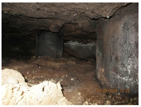
图4:查尔斯湖港口的暴露木材桩
We first performed low-strain integrity testing on a timber pile that the contractor extracted and was cut to a known length. The top graph of Figure 5 shows this data. Testing a pile of known length allowed us to estimate a wave speed for the timber piles. We then performed the same testing on three additional piles to evaluate both integrity and estimate pile lengths. The bottom graph in Figure 5 shows the data for one of the tested pile. With the relatively large variation in possible wave speed for timber piling, performing low-strain integrity testing on a known length and then obtaining clear toe responses on three additional pile with similar wave speeds gave us relatively high confidence in the wave speed we were using.

This concludes Part 1 of our discussion of how low-strain integrity testing can be used to help determine pile length and integrity of unknown deep foundation elements. Please look for Part 2 of this series, in which will discuss additional test methods and case studies of unknown or undocumented deep foundations.
要了解地面运输项目的深层基础,您可以为我们的现场网络研讨会注册到桥梁及以后!深层基础和地面运输项目于6月10日。我们希望你加入我们!
贾斯汀汉森项目工程师
P:913-647-5020E:[电子邮件受保护]
Matthew Glisson校长,主要工程师
P:314.569.9883E:[电子邮件受保护]